
To inspect cylindrical lathe work for concentricity, straightness, and T.I.R. (Total Indicator Runout), you will typically use a combination of dial indicators, V-blocks or centers, and surface plates. Until now, these tools were not adjustable (like the Insize 6888 V-Blocks).
The innovative AVB line features critical adjustments for small and large parts, without damaging delicate finishes, eliminating costly rework caused by scratches during final inspection. Here's a detailed procedure and explanation of standard inspection methods.
🧰 Tools Required:
Dial Indicator (0.0001" or 0.01 mm resolution recommended)
Magnetic Base or Height Gauge
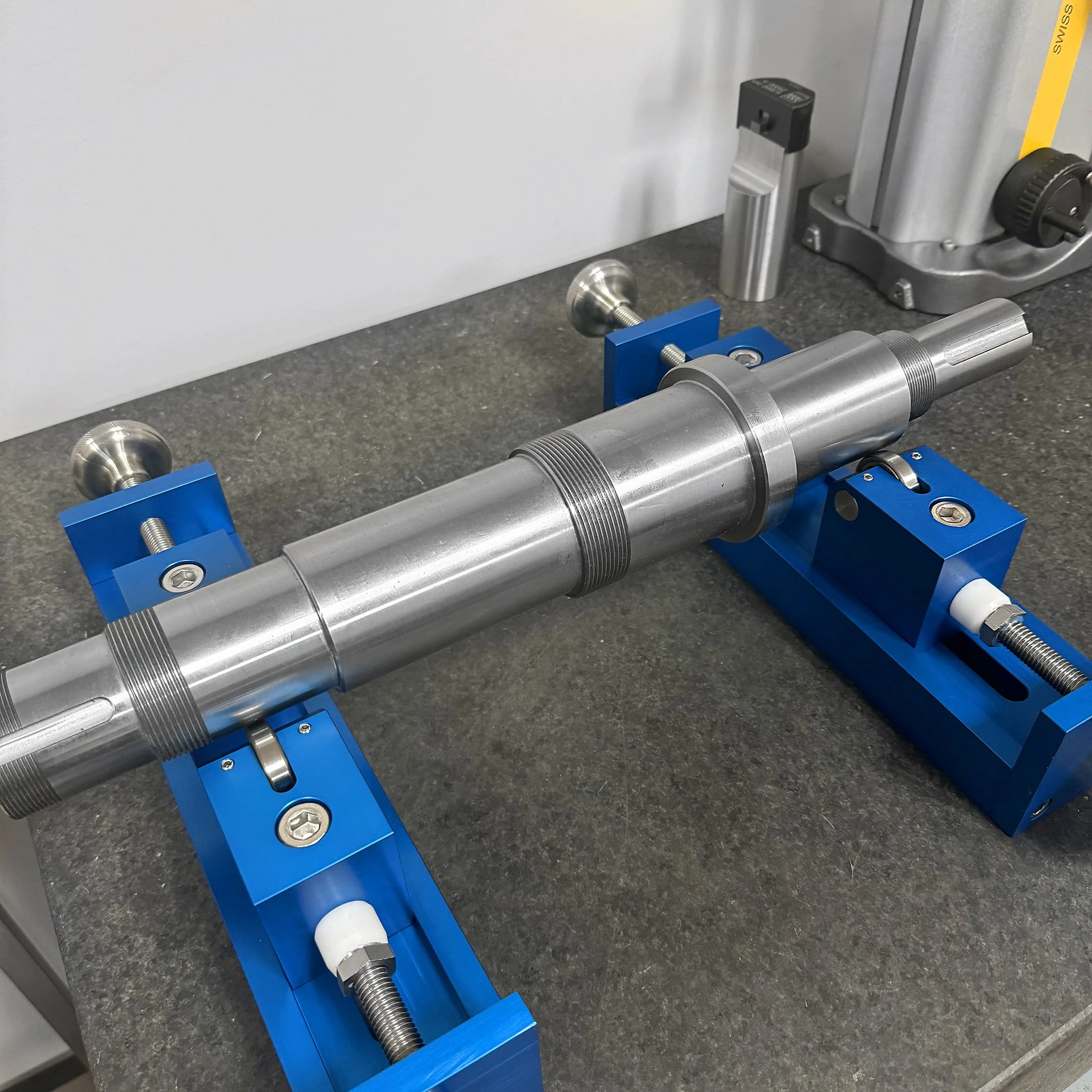
V-Blocks or Lathe Centers
Surface Plate (for bench inspection)
Test Mandrel or Precision Ground Bar (optional, for machine setup validation)
🔄 1. Total Indicator Runout (T.I.R.)
Purpose: Measures total deviation (high to low points) of a surface as it rotates — includes concentricity and surface irregularities.
➤ Steps:
Mount the cylindrical part in a chuck, collet, or between centers.
Place the dial indicator against the surface to be measured (usually OD).
Rotate the part slowly (by hand) 360°.
Record the maximum and minimum reading on the indicator.
➤ Formula:
T.I.R.=Max Indicator Reading−Min Indicator Reading\text{T.I.R.} = \text{Max Indicator Reading} - \text{Min Indicator Reading}T.I.R.=Max Indicator Reading−Min Indicator Reading
A T.I.R. of 0.0005" or less is typical for high-precision turning.
🎯 2. Concentricity
Purpose: Measures how closely the center axis of one feature (e.g., a bore or shaft) aligns with another reference feature.
➤ Steps:
Identify the reference axis (usually the OD or a ground journal).
Use V-blocks or centers to support the part.
Indicate the target feature (e.g., an ID bore) relative to the reference.
Rotate the part and record runout — this runout represents concentricity error.
Note: True concentricity (per GD&T) often requires a CMM because it is a derived median axis measurement—not just runout.
📏 3. Straightness
Purpose: Verifies that the cylindrical surface is not bowed or warped along its length.
➤ Method A: Dial Indicator on V-Blocks:
Place the part on two V-blocks set far apart.
Position the dial indicator at different axial locations (along the length).
Roll the part and note runout at each location.
Large variation between sections suggests bending or warping.
➤ Method B: Optical Comparator or Surface Plate:
Use a surface plate and height gauge with a test indicator.
Sweep along the top surface of the shaft.
Any height variation reflects straightness deviation.
✅ Inspection Tips
Always zero the indicator before taking measurements.
Rotate slowly and evenly—no jerky motion.
Ensure clean, burr-free surfaces.
For T.I.R. on internal bores, use a bore gauge or small-diameter test indicator.
If part is long or heavy, support with tailstock or steady rest to prevent sag.
📊 Example Report Format:
FeatureLocationT.I.R. (in)Concentricity (in)Straightness Deviation (in)Outer DiameterJournal 10.0003-0.0002Inner BoreMid-section0.00050.00040.0001Full Shaft Length---0.0008
If you're inspecting for a specific tolerance or GD&T spec (like true position or runout relative to a datum), let me know and I can tailor the inspection procedure or reporting method accordingly.